- Science Toys
- Magnetism
- Electromagnetism
- Electrochemistry
- Radio
- Thermodynamics
- Aerodynamics
- Light and optics
- Simple laser communicator
- Make your own 3D pictures
- Making permanent rainbows.
- A solar powered marshmallow roaster
- Make a spectroscope from a CD.
- The impossible kaleidoscope
- Make a solar hotdog cooker
- Exploring invisible light
- A high resolution spectrograph.
- Time-lapse photography.
- High speed photography.
- Stacking photos for high depth of field.
- Biology
- Mathematics
- Computers and Electronics
Fun with solderless breadboards
When building a circuit for the first time, it is often very useful to have a way to quickly change connections or parts placement. In the early days of electronics, quick, temporary circuits were sometimes built on a piece of wood, similar to the boards that bread is sliced on. Building a first prototype came to be known as breadboarding. Back when components like tubes and transformers were large and long wires were common, it was easy to solder and unsolder connections. Modern circuits, made with small transistors or many legged integrated circuits, are much harder to solder and especially to unsolder. To make life easier, solderless breadboards were invented. These are blocks of plastic with holes into which wires can be inserted. The holes are connected electrically, so that wires stuck in the connected holes are also connected electrically. The connected holes are arranged in rows, in groups of five, so that up to five parts can be quickly connected just by plugging their leads into connected holes in the breadboard. When you want to rearrange a circuit, just pull the wire or part out of the hole, and move it or replace it.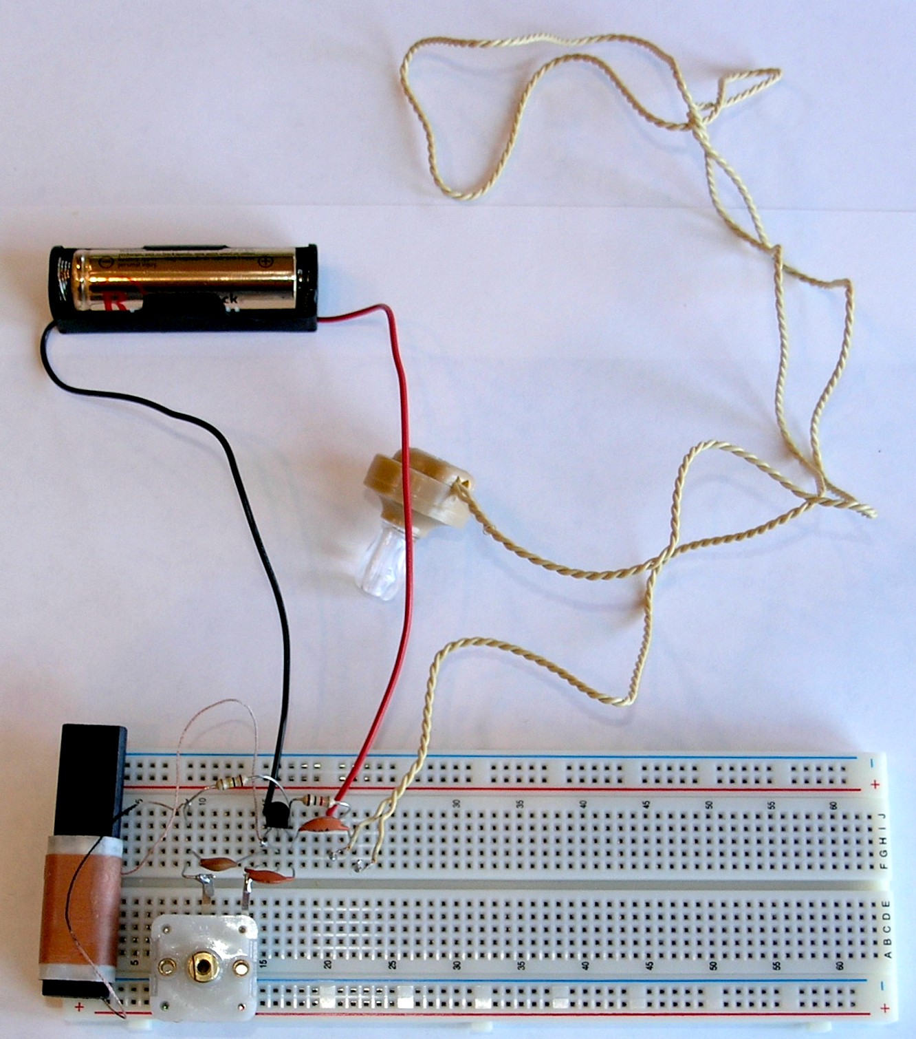
Click on photo for a larger picture
In the photo above, we have a complete radio, with an antenna coil, a tuning capacitor, a three-legged integrated circuit, a battery, and earphone, two resistors, and three capacitors. This radio is the Three Penny Radio kit from the Scitoys Catalog, which is usually soldered, using three pennies as convenient places to connect the various parts. The three-penny radio needs these parts:
- An antenna coil
You can wind one by hand, but in this project we use a much smaller coil with a ferrite rod inside, from our catalog. - An MK484-1 AM Radio Integrated Circuit
This is the heart of the radio. We carry it in our catalog. - A Piezoelectric earphone
Also in our catalog. - A tuning capacitor
We use a variable capacitor, from 0 to 160 microfarads. We have it in our catalog. - A 100,000 ohm resistor
This resistor will have four colored bands on it. The colors will be brown, black, yellow, and gold. - A 1,000 ohm resistor
This resistor will also have four colored bands on it. The colors will be brown, black, red, and gold. - A 0.01 microfarad capacitor
This capacitor will be marked something like ".01M" or "103". - Two 0.1 microfarad capacitors
These capacitors will be marked something like ".1M" or "104". - A 1.5 volt battery
- A 1.5 volt battery holder
And, in this version: - A solderless breadboard
Also in our catalog. and later: - A printed circuit board
Also in our catalog.
Click on photo for a larger picture
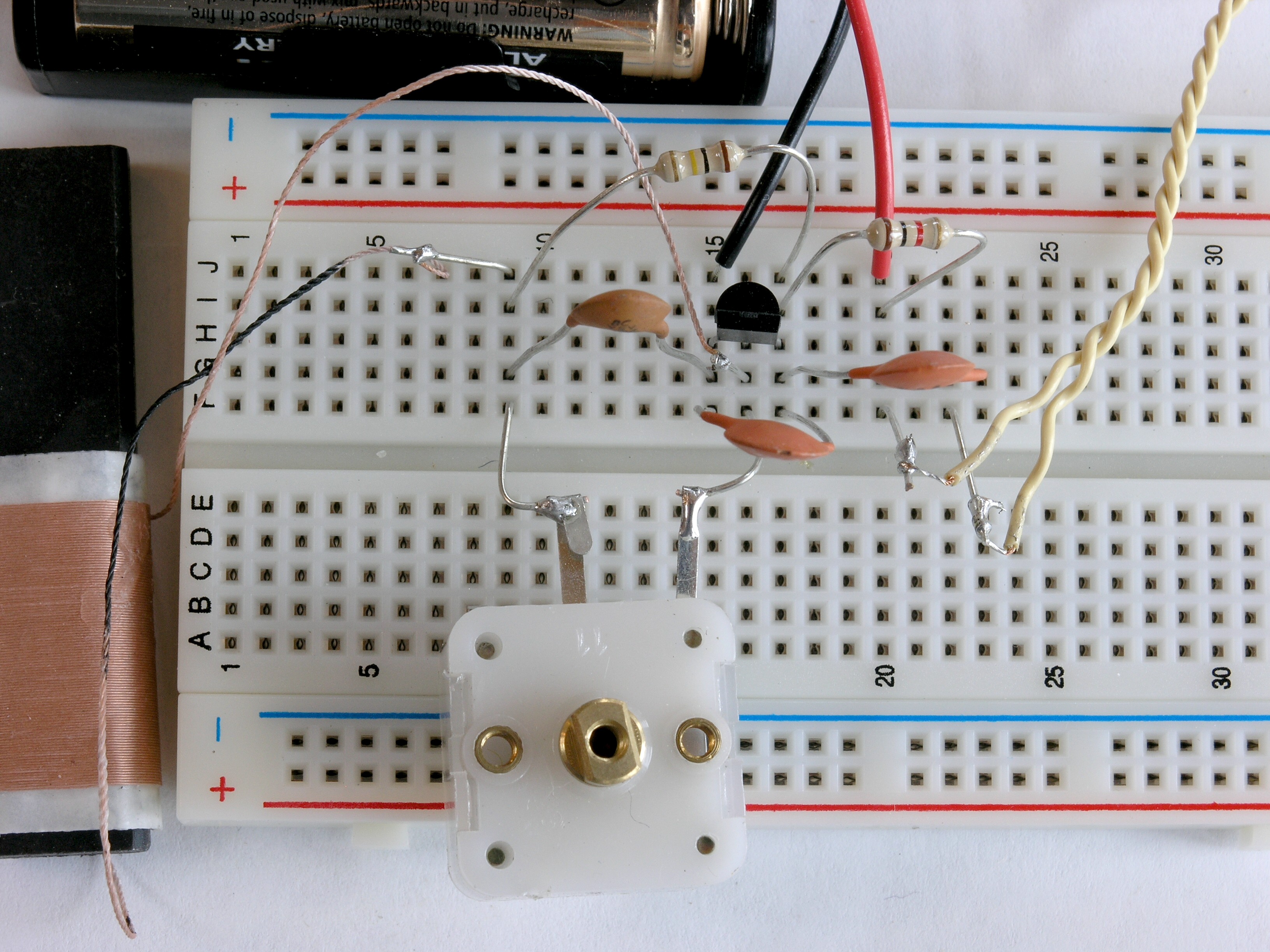
In the closer view, you can see that the parts we want to be electrically connected are plugged into one of the five holes marked A, B, C, D, or E, (or in this case, where we used the second half of the board, marked F, G, H, I and J) in rows marked 1 through 63. Along each side of the breadboard are two strips of power supply rails, making it convenient to connect a battery when many parts need power. In our simple radio, only one part needs power, so it is convenient to simply plug the battery wires directly into the main circuit area. The solderless breadboard is designed to accept the leads from parts such as resistors, integrated circuits, transistors, and other parts with round solid wire for leads. Some of the parts for the radio have thin, stranded wire that is not stiff enough to poke into the holes, or (like the variable capacitor) have flat strips of metal that are too big to fit into the holes. For these parts, we solder their leads to pieces of wire cut from the leads of other parts, such as resistors or capacitors. Most such parts have leads that are longer than we needed anyway, so they will fit more snuggly onto the board with shorter leads. In the photo you can see that the antenna coil, the variable capacitor, and the piezoelectric earphone have wires soldered to their leads to make it easy to plug them into the breadboard.

Click on photo for a larger picture
Having the holes arranged in a labeled grid is convenient for describing the parts layout. We can list each part, and the letter and number of each lead:
- Antenna coil: J9 and G16
- Tuning capacitor: F9 and F16 (only the two rightmost leads are used)
- MK484 IC: H15, H16, and H17 (flat side facing row G)
- 100,000 ohm resistor( brown, black, yellow): I9 and J17
- 1,000 ohm resistor (brown, black, red): I17 and I20
- 0.01 microfarad capacitor (marked 103 or .01M): G9 and G15
- 0.1 microfarad capacitor (marked 104 or .1M): F15 and F17
- 0.1 microfarad capacitor (marked 104 or .1M): F17 and F22
- Piezoelectric earphone: F20 and F22
- Negative battery wire (black): J15
- Positive battery wire (red): J20
Making the circuit permanent
Solderless breadboards are great for building circuits the first time, and getting them to work, or experimenting with design changes. But when you get the circuit working the way you want it to work, you will want to copy it to a more permanent form, by soldering it onto a circuit board. The printed circuit boards we carry in our catalog also have five holes that are electrically connected. The holes are grouped into 3 holes and 2 larger holes, to make it convenient to connect larger wires leading out from the board, for power connections and other external parts. The radio shown below was built by a student as a first exercise in soldering: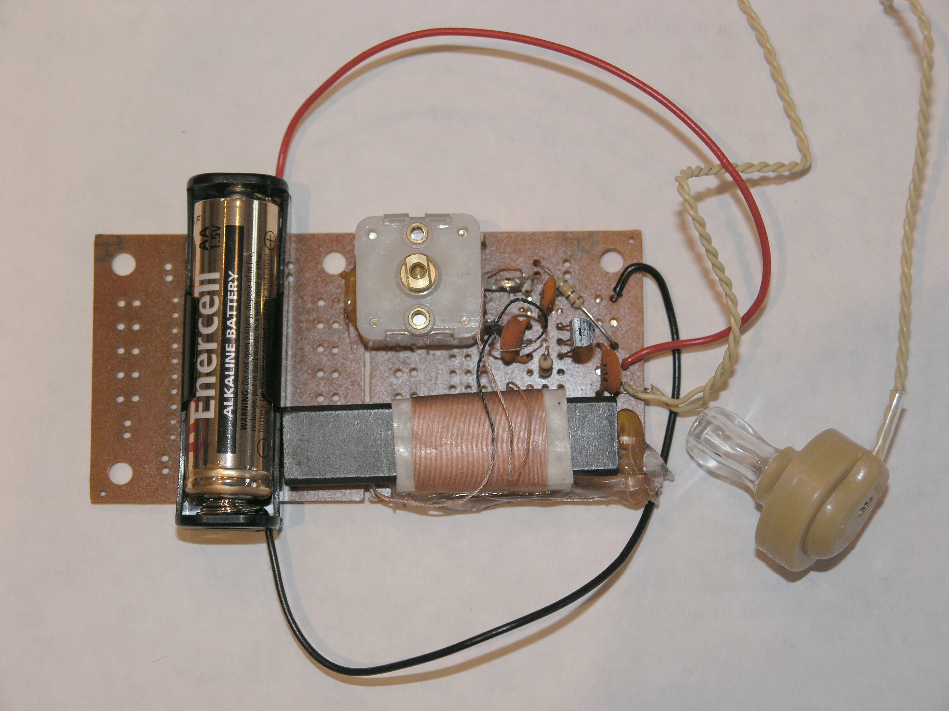 Here is the back side:
 It worked the first time!
Next:
A simple audio amplifier.
Del.icio.us
It worked the first time!
Next:
A simple audio amplifier.
Del.icio.us
- Science Toys
- Magnetism
- Electromagnetism
- Electrochemistry
- Radio
- Thermodynamics
- Aerodynamics
- Light and optics
- Simple laser communicator
- Make your own 3D pictures
- Making permanent rainbows.
- A solar powered marshmallow roaster
- Make a spectroscope from a CD.
- The impossible kaleidoscope
- Make a solar hotdog cooker
- Exploring invisible light
- A high resolution spectrograph.
- Time-lapse photography.
- High speed photography.
- Stacking photos for high depth of field.
- Biology
- Mathematics
- Computers and Electronics
Some of my other web sites:

Send mail to Simon Quellen Field via sfield@scitoys.com